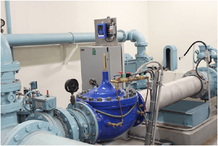
ARC valve stands for the Automatic Recirculation Valve. The device is a multifunctional valve with a primary purpose of ensuring that a pre-determined minimum flow is acquired via the centrifugal pump of the machine. This process should be standardized at all times. The centrifugal pumps may suffer from overheating as well as cavitation. They can also be permanently damaged. For that reason, it’s essential to understand the operational principles of an ARC valve.
- Operating The ARC Valve
The ARC valve is sensitive. Its discs play a key role in ensuring that the flow to the pump is at its minimum point. As such, it’s essential to note that the valve isn’t as sensitive to any outer pressure. This attribute helps in ensuring that there’s a steady flow through the pump regardless of the pressure. For example, if the valve disk is at its full operational capacity, the bypass will close, thereby reducing the flow.
- Disintegrating The Technique Of The Flow
The flow of materials in the ARC valve is directed to the bypass, which is an important element of the device. The orifices control the entire disc movement. The flow proceeds to an annulus before reaching the ARC Valve outlet. The ARC valve subjects the flow of its contents in one main direction. It also eliminates the chances of flashing in addition to cavitation.
- The Direction Of Flow In ARC Valve
The ARC valve and the external pressure regulator ensure that the flow in the device is complete. When the flow of these materials in the ARC valve increases, the disc lifts to reduce the recirculation flow. The flow in the system is, therefore, higher compared to the flow in the pump of the automatic recirculation valves.
- How The Centrifugal Pump Protects Scenarios
The centrifugal pump of the ARC valve operates by transforming the mechanical energy of the device into pressure energy. The process is facilitated by the centrifugal force, which facilitates the rotation of the impeller. The impeller acts on the fluid in the ARC pump. To avoid overheating, the pump needs a minimum flow of fluids.

- The Non-Return Scenario
In the non-return scenario, the pump does not have backflow prevention. The product will easily flow back via the valves. The non-return valve will be placed after the outlet of the pump. Usually, a reservoir will be used in taking various pumps out. This is in cases with no process demand.
- The Continuous Flow
In this phase, a manual bypass can be included in the device to allow a minimum flow back into the pump inlet. The system is effective and also consistent in operation. Therefore, it’s inefficient and costly when the energy cost is factored in.
- The Control Valve Scenario
This is a highly effective, comprehensive control valve solution. In this phase, an ARC flow control valve is linked to a flow meter. The valves allow the metering of the mainline of flow. The main flow decreases as the control valve opens. This enhances the movement of the minimum flow. Nonetheless, it’s a capital intensive solution that needs the input of metering equipment.
- The ARV Solution
In this phase, the system combines the nonreturn valve with the bypass valve. This valve then closes when there’s hardly any flow. It automatically opens the bypass line. The mainline of the valve then take some flow. The bypass line should be open at this moment.
Conclusion
An automatic recirculation valve is a multifunctional valve created to ensure that there’s minimum calculated flow via the centrifugal pump. It’s an essential process since the centrifugal pump suffers from cavitation. It’s crucial for professionals to understand the operating techniques of an automatic recirculation valve.
